ACTIVE POWER AND REACTIVE POWER
Electrical appliances in residential homes have an electrical power in watts, which if multiplied during the use of the appliance, electricity is obtained in terms of watts per hour, and if this number is divided by 1000, it is obtained in kilowatt-hour. Real work in electricity grids is done by active power. By converting electrical energy into other forms of energy such as heat, rotation or motion, leads to real work to be done. The current and voltage are completely in-phase in active loads. Reactive power does not do any useful work and generate electric and electromagnetic fields. This power is not consumed and will be continuously injected from the grid to the load and re-entered the grid from the load. Reactive power is measured in units of volt-ampere reactive (VAR), and if divided by 1000, it is obtained in kilowatts.
A PRACTICAL EXAMPLE
Regarding to the existence of at least one refrigerator in the majority of urban and rural residential houses, a test has been done in the company’s laboratory in cooperation with Niroo Research Institute which shows the results of capacitor placement in the refrigerator. The numbers are the result of normalized statistical societies which Samplings performed in different consumption peaks and various brands of refrigerators.
|
Parameters in the circuit with a capacitor |
Parameters in the circuit without a capacitor |
Measured parameters
|
Rank |
| 5μF |
6.3μF |
9μF |
12μF |
17μF |
| 228 |
229 |
229 |
229 |
228 |
228 |
Voltage |
(V) |
1 |
| 49.9 |
49.91 |
49.91 |
49.99 |
49.9 |
49.9 |
Frequency |
(Hz) |
2 |
| 0.87 |
0.84 |
0.81 |
0.73 |
0.82 |
1.13 |
Current |
(A) |
3 |
| 0.75 |
0.82 |
0.85 |
0.98 |
0.91 |
0.57 |
CosΦ |
4 |
| 0.149 |
0.156 |
0.16 |
0.162 |
0.168 |
0.146 |
Apparent Power |
(kW) |
5 |
| 0.197 |
0.19 |
0.179 |
0.163 |
0.078 |
0.256 |
Reactive Power |
(kV) |
6 |
| 0.129 |
0.111 |
0.093 |
0.03 |
0.078 |
0.212 |
Reactive Power |
(kVAR) |
7 |
As shown in the table above, in order to reach cosϕ to 0.85, it must be used a 9 microfarad capacitor. As a result, the reactive power in 9 microfarad capacitor is 0.093 and is injected into the circuit in pre-phase.
Diagram of reactive power correction due to capacitor placement in the circuit of a domestic refrigerator
The area under the diagram shows that if a capacitor with a capacitance of more than 12 microfarads is used, the capacitor becomes a consumer.
SAVING FROM CAPACITOR PLACEMENT OF POWER FACTOR CORRECTION IN SINGLE-PHASE DOMESTIC METERS
| Annual reactive power generated from capacitor placement (kVAR) |
Simultaneity coefficient |
Days of the year |
Loading
(Hrs) |
Losses reduction
(kVAR) |
Reactive power |
Type of electric appliance |
| With a 9 μF capacitor |
Without a capacitor |
| 312 |
0.6 |
365 |
12 |
0.119 |
0.93 |
0.212 |
Refrigerator |
| 312 kVAR ̴62kWh |
Based on the above calculations, the efficiency of capacitor placement in single-phase domestic meters during the eleven years of capacitor lifetime is more than ten of times the required cost for the installation and maintenance of the capacitor.
Domestic HARMONICS FILTERING
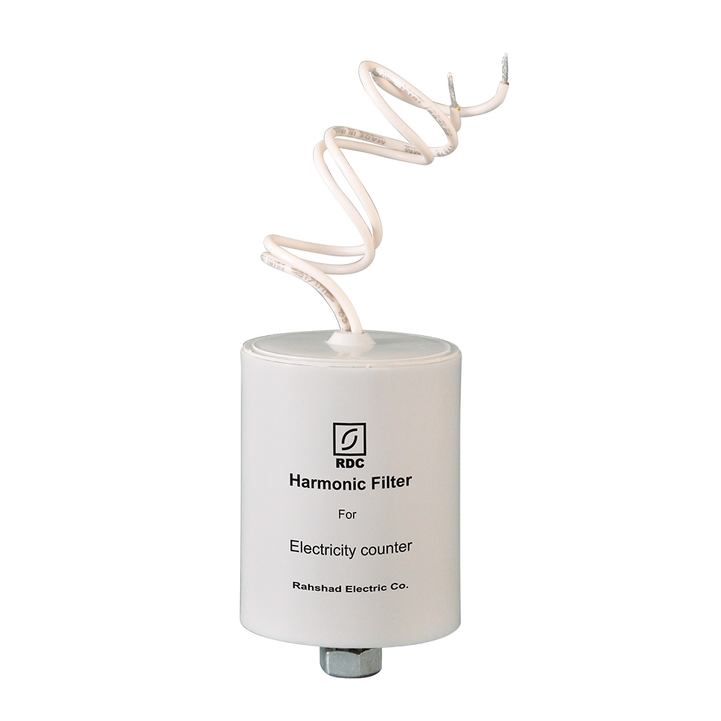
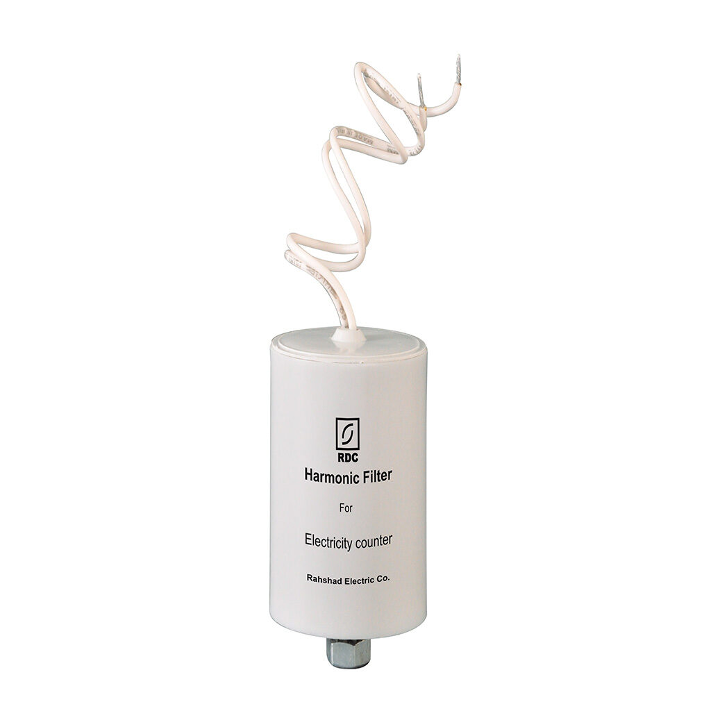
In order to relieve concerns of managers and experts in the field of electrical industry, especially Tavanir company and electricity compamies about development of non-linear loads and increasing order of domestic harmonics, this company has designed and manufactured the harmonic filter with power factor correction capacitor that can be installed in the energy meter. Regarding to the capacitor current equation (lc=2 × π × f × c ×Uc), it is revealed that under the same voltage conditions, increase in frequency causes increase in the capacitor current. For example, if the fifth amplitude of harmonics is 5% of the principal component, the current drawn from the capacitor by this harmonic is 25% of the amplitude of principal current. So existing harmonics in grid, causes serious damage to the capacitors.
The combination of inductor and capacitor will have inductive property at frequencies higher than the resonance frequency (fr) and capacitor property at lower frequencies. Therefore, we have solved the power factor correction problem in such a way that the power factor correction is done at the main frequency without disturbance of higher frequencies in the capacitor operation.
THE MAIN ADVANTAGES OF POWER FACTOR CORRECTION CAPACITORS OF RAHSHAD ELECTRIC COMPANY
- Low internal dissipation (Maximum tg δ is 20×10-4)
- In state apparent power (such as grids that have already been designed and run), more active power consumed by reducing reactive power.
- No permanent short circuit due to self-healing phenomena
- Lighter and smaller than other capacitors
- No leakage and environmental pollution due to dry type of capacitor and filling resin
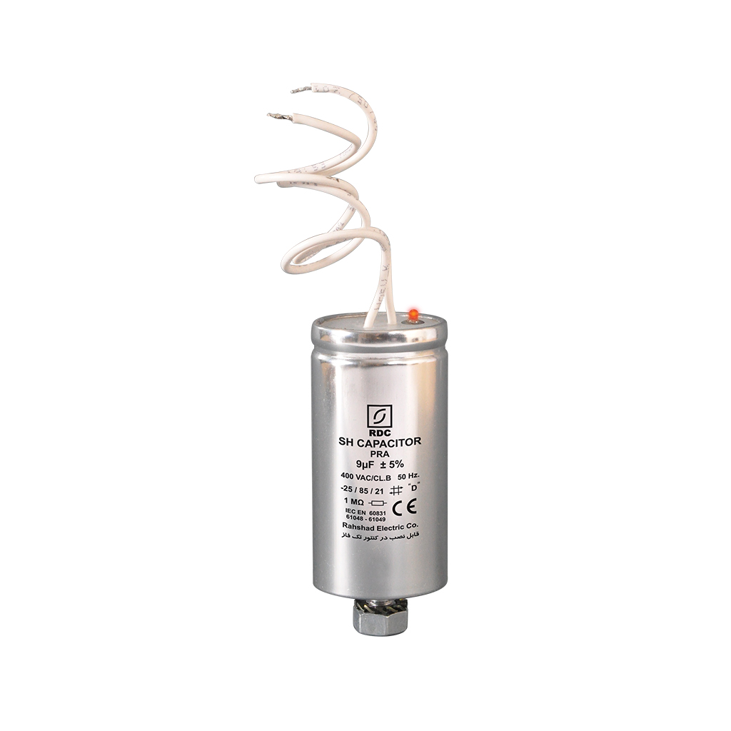
TECHNICAL SPECIFICATIONS OF POWER FACTOR CORRECTION CAPACITOR
| Capacitance (μF) |
9 μF |
| Nominal Voltage (VAC) |
250 VAC |
| Nominal Frequency (Hz) |
50-60 Hz |
| Operating Temperature (oC) |
-25 oC / +85 oC |
| Way to inform health of the capacitor (with the help of the meter reading operator) |
The signal lamp operates in such a way that it is always on in the capacitor’s health and turns off due to capacitor failure. |
| Inductive Property |
550 mH |
| Dissipation Factor (tg δ) |
Less than 20×10-4 in 50 Hz |
| Casing |
Model PRA: Plated shining aluminum for more safety |
| Model PRP: Flame retardant plastic material |
CAPACITOR LIFETIME
Class A: 100000 hours equal 10 years
Class B: 30000 hours equal 3.5 years


Reviews
There are no reviews yet.